
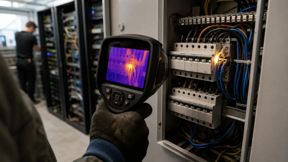
Most switchboard failures give no advance warning. They announce themselves by the smell of hot insulation on a Friday afternoon, by a tripped main breaker, or by browned plastic around a terminal nobody has touched in a year. And yet the fault had been signalling the whole time — through heat. Nobody was measuring it.
Thermal imaging allows the thermal behaviour of equipment to be monitored without contact while it is under operating load; safe access to the internal parts of a switchboard always has to be assessed for the specific equipment and working procedure. It is also a method that can be turned into very expensive coloured wallpaper if the survey is done at the wrong time and the report contains nothing but pictures. Let’s go through what a thermal camera actually sees inside a switchboard, what is guaranteed to escape it, which findings come up most often, and how to recognise a survey that will actually give you something to repair.
What actually heats up inside a switchboard
The physics is simple and unforgiving: every resistance dissipates power as current passes through it, following P = R · I². Doubling the current therefore means four times the heat — and a joint that looks perfectly fine during the morning start-up can be tens of degrees hotter at the afternoon peak. That is exactly why thermal imaging is done under load, and why results from unloaded equipment cannot be taken seriously.
The contact resistance of a joint rises for a handful of recurring reasons:
- A loose joint. A bolted connection loses its clamping force through thermal cycling and vibration. With aluminium conductors and busbars, material creep is added to the mix — under the sustained pressure of the terminal, aluminium slowly “gives way” and the joint loosens without anyone ever touching it.
- Oxidation and an improper Al–Cu transition. Aluminium oxide is an insulator and forms instantly on a freshly stripped conductor. Direct contact between aluminium and copper in a damp environment is also subject to electrochemical corrosion — hence the use of terminals and cable lugs designed for aluminium, with the appropriate treatment and the specified tightening torque.
- A badly crimped cable lug. Crimping with the wrong profile or an ill-fitting crimping tool produces a joint that holds mechanically but not electrically.
- A burnt contact in a switching device. Contactors, switch-disconnectors and circuit breakers have a limited switching life. The harshest duty falls on contactors in power-factor correction boards, which switch capacitor banks with high inrush currents.
- An overloaded neutral conductor. Single-phase non-linear loads — switched-mode computer power supplies, LED drivers, machine electronics — generate third harmonics. These do not cancel at the star point but add up, so the current in the neutral can exceed the current in the individual phases. Meanwhile the switchboard looks “only lightly loaded”.
Photovoltaic installations add the DC side: MC4-type connectors from different manufacturers that mate mechanically but are not intended to be paired with each other, string fuse holder contacts and DC switch-disconnectors. A high-resistance fault or a series arc need not produce enough current to trip ordinary overcurrent protection. A finding of this kind calls for safe, professional verification and repair.
Thermal imaging and a scheduled inspection answer different questions
A scheduled inspection assesses the safety of the electrical installation within a defined scope: visual examination, measurement (insulation resistance, fault loop impedance, continuity of protective conductors, testing of residual current devices), a check of the documentation and an evaluation. The framework for reserved technical electrical equipment is set by Act No. 250/2021 Sb. (Czech act on occupational safety in relation to reserved technical equipment) and Government Regulation No. 190/2022 Sb., while inspection intervals in practice are governed by ČSN 33 1500 and ČSN 33 2000-6 ed. 2. The output is an inspection report — covered in more detail in the article on switchboard inspections and in the overview of electrical installation inspection intervals under ČSN 33 1500.
Thermal imaging answers a narrower but highly practical question: is unusual heat being generated right now, under real load, anywhere in here? It will not measure insulation resistance, will not test an RCD, will not confirm the continuity of a protective conductor and will not replace an inspection report. What it will catch is change that has arisen since the last inspection — and in a typical company, several years usually pass between electrical installation inspections, depending on the environment.
Alongside this, there is the general duty of an employer to identify and evaluate risks and to adopt measures to eliminate them under Section 102 of the Labour Code. Thermal imaging is one of the tools for catching the risk of fire from electrical equipment before it materialises — not an obligation in its own right.
The two checks therefore complement each other: an inspection evaluates safety within a defined scope, thermal imaging monitors the thermal condition under load, and follow-up electrical measurement helps pin down the cause of any anomaly found.
Typical findings and what usually lies behind them
| Finding on the thermogram | Likely cause | What to verify |
|---|---|---|
| One joint is hotter than the neighbouring joints in the same row | Loose terminal, oxidation, badly crimped lug | Tightening torque per the manufacturer, condition of the contact surface and conductor |
| One phase hotter throughout a branch | Unbalanced load, poorer contact in one phase | Currents in individual phases, voltage drop across the device |
| A whole conductor or device heats up evenly | Overload, undersizing, high temperature inside the enclosure | Actual current, cross-section, rated data and permissible temperature rise |
| A local hot spot on a breaker, contactor or switch-disconnector | Worn internal contact, burning after a short circuit | Comparison of the incoming and outgoing side, number of operations, history of short circuits |
| Hot fuse holder or fuse-link blade | Loss of contact spring pressure, contamination, unsuitable fuse-link type | Condition of the contact surfaces, correct characteristic and size of the fuse-link |
| Warm neutral conductor without matching phase loading | Imbalance or third harmonics from electronics | Current in N and, depending on the situation, a power quality analysis |
| Hot contact on a busbar (comb) connector under a breaker | Comb tooth not fully seated, incorrectly shortened busbar | Busbar offset, tightness, condition of the contact |
It is not only high temperature that should raise suspicion. An unexpectedly cold branch can mean no current is flowing through it — a blown fuse, a broken conductor, a machine taken out of service that nobody knows about.
In the other direction, plenty of hot spots are entirely normal: heat sinks on variable-frequency drives, braking resistors, transformers, detuning reactors in power-factor correction and power supplies are supposed to run hot. A finding is worthless without knowledge of how the equipment is built — which is why it always has to be confirmed by measurement, and why you repair the cause, not the colour.
What a thermal camera cannot see
Infrared radiation does not pass through sheet metal, a plastic cover or most doors. An image of a closed switchboard will flag pronounced heating of the enclosure as a whole, but it will not show a small defective joint inside. The exception is infrared inspection windows, fitted into the doors so that measurements can be taken without opening them — although their usefulness ends where their field of view does.
A survey may also fail to reveal:
- a circuit that was not running at the time of the check, or was loaded only briefly,
- damaged insulation that is not yet showing up as heat,
- a missing or interrupted protective conductor,
- a non-functioning protective device with no thermal signature,
- an intermittent fault that did not appear during the visit,
- a component hidden behind another device, a trunking run or a bundle of conductors.
Hence the most common mistake when ordering: thermal imaging at the weekend, during a shutdown, or at a time when the plant is idle. The switchboard then looks flawless purely because only a fraction of the operating current is flowing through it.
When to survey so that the image means something
The first step is to decide which switchboards are to be surveyed and in what operating mode. In manufacturing, the decisive factor is usually machines, the compressor and the ventilation system all running at once. In an office building, the peak often falls in summer with air conditioning, the kitchenette and vehicle charging in play. For photovoltaics, a survey makes sense in good irradiance when the plant is genuinely generating — and for the thermography of photovoltaic arrays there is a dedicated technical specification, ČSN EN IEC 62446-3.
In practice, a load of roughly 40 % of rated current is taken as a sensible minimum; below that, the risk grows that a fault will not show up at all. A measured temperature difference can, if the current is known, be roughly extrapolated to rated load using that same quadratic relationship — but extrapolation never replaces measurement in real operation.
The technician should record at least the designation and location of the switchboard, the operating state at the time of the check, the currents in the important branches and individual phases, the ambient temperature, the emissivity setting, the thermogram together with a matching conventional photograph, and an unambiguous identification of the defective component.
Removing covers and working in the vicinity of live parts is a job for someone with the appropriate electrical qualification, a risk assessment and protective equipment against the effects of an electric arc. A company’s own employee should not be removing internal covers just to take a photograph. If you don’t have such a person on site, we can carry out both the thermal imaging of switchboards and the follow-up inspection — including current measurements and a report you can actually work with.
How to read a thermogram without being misled by the colours
Red on its own does not mean disaster. A thermal camera automatically stretches the colour scale across the temperature range in the scene, so a two-degree difference can look dramatic — while in another image an equally red spot is fifty degrees hotter. Without a temperature scale and numerical values, the image is just a picture.
What matters in the assessment:
- the actual measured temperature at the point,
- the difference against a comparable component under the same load (a reference joint on the neighbouring phase),
- the current at the time of measurement,
- the ambient temperature and the temperature inside the enclosure,
- the permissible temperature rise for that device according to the manufacturer.
Beware of shiny metals. Polished copper and aluminium have emissivity in the hundredths, so instead of their own temperature they reflect their surroundings — the technician, the lights, neighbouring hot components. A matt surface, by contrast, has emissivity around 0.95 and measures reliably. A suspicious spot therefore needs to be verified from another angle and assessed in the context of how the equipment is built.
The report should contain numbers, not just images dropped into a PDF: temperature, reference, load, emissivity and unambiguous identification of the component. What a well-prepared output from an electrical check looks like in general is covered in the article on reading an inspection report.
When to book a thermal survey
There is no universally prescribed interval for the thermographic survey of switchboards. The frequency follows from the load, the environment, how critical the equipment is, the manufacturer’s instructions, the maintenance plan and any requirements in the insurance policy. An annual interval for main switchboards and a longer one for lightly loaded sub-distribution boards is the usual compromise — and it belongs in the maintenance plan, not in one person’s head.
A specific reason to book one typically arises:
- after expanding production or connecting a new machine,
- after installing photovoltaics, charging stations, air conditioning or a heat pump,
- when breakers trip or fuses blow repeatedly with no obvious cause,
- with voltage fluctuations, unexplained outages or the smell of hot insulation,
- ahead of a period of regularly high load (summer peak, seasonal operation),
- in older switchboards with no ongoing diagnostics and no operating documentation,
- wherever a switchboard failure would halt production, cooling, a server room or another critical operation.
With photovoltaics, thermal imaging naturally sits alongside the other in-service checks between inspections — the DC side and the inverter warrant attention more often than a distribution board in an office.
If you smell burning, hear crackling, see smoke, find a browned cover or the main protection trips repeatedly, don’t wait for a scheduled survey. Do not open the equipment; deal with the situation without delay through an electrician or an emergency call-out service.
How to spot a usable quotation and what drives the price
A quotation for “thermal imaging of the building” with no scope stated cannot be compared with anything. So tell the supplier up front how many switchboards there are and where they are located, whether they can be opened during operation, and when they are typically under the heaviest load.
Ask whether the price includes both conventional and thermographic images, measurement or recording of the load, unambiguous identification of the findings, their ranking by urgency, recommendations for further verification or repair, a final report and a follow-up measurement after the repair.
Detector resolution — 160 × 120 versus 320 × 240 pixels, say — determines how small a detail can be resolved from the same distance. On its own, though, it is no substitute for correctly set emissivity, proper focus or the technician’s experience. More important than the make of camera is the combination of thermographic practice with knowledge of electrical equipment; if the thermographer is not qualified to work safely at an open switchboard, the contract has to include cooperation with someone who is.
For a small job the price runs to the low thousands of Czech crowns; for a site with dozens of switchboards, a detailed report and measurement outside normal working hours, expect the higher thousands to tens of thousands. It cannot honestly be set by counting doors — the distance between buildings, the need for an escort, the extent of current measurements, the quality of the output and the follow-up check all feed into it. A suspiciously cheap quotation usually means a quick round of photographs of closed enclosures; before ordering, ask for an anonymised sample report.
What to do with a finding
A thermographic report is not an instruction for someone to tighten a terminal in a live switchboard. The finding should be taken over by an electrician, who determines the cause and proposes a safe repair procedure — for most joints the correct answer means isolating the circuit, checking the contact surfaces and tightening to the specified torque, not tightening “by feel” under voltage.
A damaged joint often calls for more than tightening: replacing the terminal, the cable lug, a length of conductor or the entire device whose contacts are burnt. With overloading, the answer lies in the load and the sizing, not in cooling the enclosure with an added fan.
After repairing a serious finding, a follow-up thermogram under comparable load makes sense. Only then will you see whether the anomaly has genuinely gone — and it is the cheapest thing you can add to the repair order.
To have a specific quotation prepared, have ready the site address, the approximate number of switchboards, photographs of their rating plates, and information on when the equipment runs under normal and under maximum load.
Frequently asked questions
Does the switchboard have to be switched off for thermal imaging?
No — quite the opposite, the survey only makes sense under a representative load. Opening covers during operation, however, is strictly a job for someone with the appropriate electrical qualification and a safe working procedure.
Can measurements be taken through the closed switchboard door?
You will measure the surface temperature of the enclosure, which only reveals pronounced cases. Neither sheet metal nor most plastics let infrared radiation through, so a small defective joint inside stays hidden. The answer is safe access to the components or an installed infrared window.
What temperature already means danger?
There is no single universal threshold. What matters is the type of component and its permissible temperature rise according to the manufacturer, the ambient temperature, the current load and the difference against a comparable component under the same load.
Does thermal imaging replace a scheduled electrical inspection?
It does not. It is a diagnostic method focused on thermal behaviour; an inspection assesses the electrical installation within a defined scope, includes electrical measurements and ends with an inspection report.
Is thermal imaging worthwhile on a new switchboard?
Yes, particularly once the plant has been brought into normal operation. It will reveal an assembly error, an untightened joint or an unsuitable load distribution that could not have shown up on unloaded equipment.
Sources for this article
- Electrical installation and switchboard inspections – a SOHE service.
- Switchboard inspections – the scope, content and course of an inspection of the switchboard itself.
- Electrical installation inspection intervals under ČSN 33 1500 – how the intervals are derived from the environment and the type of building.
- How to read an electrical inspection report – what the listed defects mean and how to deal with them.
- Act No. 262/2006 Sb. – the Czech Labour Code; Section 102 governs the identification and evaluation of risks and measures to eliminate them.
- Act No. 250/2021 Sb. – on occupational safety in relation to the operation of reserved technical equipment, including electrical equipment.
- Government Regulation No. 190/2022 Sb. – on reserved technical electrical equipment and the requirements for ensuring its safety; it governs, among other things, inspections and examinations.
- ČSN 33 1500, ČSN 33 2000-6 ed. 2 and ČSN EN IEC 62446-3 – the intervals and scope of electrical installation inspections, and the thermography of photovoltaic arrays respectively (these standards are not freely available).
This text is informational and does not replace legal advice. The specific regime for checks, thermographic surveys and switchboard inspections needs to be set according to actual operation, the manufacturer’s documentation, the environment of use and a risk assessment.
We carry out thermal imaging of switchboards during operation, with current measurements and a report that contains numbers and clearly marked components to repair — and we can follow a finding straight through to an electrical installation inspection. Tell us how many switchboards you have and when they are under the heaviest load, and we’ll prepare a specific quotation: a no-obligation enquiry or info@sohe.cz.